![]()
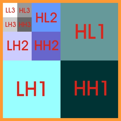
Now the decomposed image will have maintained the relative original image
size while effecting a separation of approximations and details in to 4 subbands.
Maximum energy is concentrated in LL and minimum energy is HH.
More in LH and less in HL.
With respect to pixels majority of the pixels in LL have high energy and
a minority of pixels in HH have high energy.
To save the image as a compressed image after decomposition, we need to
store only those pixels with high energy content, and most importantly their
relative positions.
Very easily, we comprehend that most of the pixels in LL will be stored
and very few of the pixels in HH will be stored.
But how to maintain the positions of these high-energy
pixels?
This problem is solved by the ZEROTREE approach to a decomposed image.
Consider a three level decomposition.
As is the approach in DWT, only approximations are
subjected to further decomposition. Common sense dictates it.
Let us consider a pixel x
with value e in LL3. If ½e½<
th, where th is a threshold value, then there is a large
probability that the pixels in other subbands corresponding to the pixel x
in LL3 will also have absolute values < th.
Then pixel x is taken as a starting node and a zerotree path is constructed as shown.
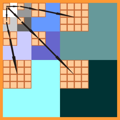
If all pixels in the zerotree path
have absolute values < th a zerotree is said to exist.
These tree are called zerotree
because values of the pixels making up these trees do not contribute
significantly during reconstruction and may be taken as ‘0’s. But their
positions are extremely important and this is where zerotrees play a role in
image compression.
Then pixel x is marked as a
zerotree node by putting ‘0’ in a significance map. The
other pixels in the zerotree are marked as descendents.
If any of the pixels in the
zerotree path has absolute value > th, the zerotree ceases to exist
and the starting node x is marked as an isolated zero by putting ‘1’
in the significance map.
If
÷
e÷
³
th then the pixel is marked as a significant ‘2’ or ‘3’
in the significance map, ‘2’ for positive values and ‘3’
for negative values thus eliminating the necessity of a sign bit.
This is because at least two bits
are needed for marking ‘0’, ‘1’,and a significant value in
the significance map. A bit is left over and this in turn is used to indicate
the sign of the significant values thus reducing a bit in the total no of bits
needed to store a significant value.
This is the procedure to be
followed for creating a significance map.
This procedure has to be applied
to each pixel in as subband before moving on to the next subband along the scan
path.
SCAN PATH

The scan path is extremely
important, as the path along with the zerotrees are responsible for maintaining
the positions of the pixels.
Once we have the decomposed image
and its significance map we begin encoding, reducing the matrix form of
decomposed image to a continuous stream of data.
Again, we follow the scan path
starting from the first subband in the last level of decomposition.
If we come across a ‘0’
or a ‘1’ in the significance map, we encode those mapcodes
using two bits.
If we come across a ‘2’
or a ‘3’ in the significance map, we encode these map codes using two
bits as well as the significant values pertaining to a ‘2’ or a ‘3’
in the decomposed image.
This is repeated until we reach
the last subband in the first level of decomposition.
The continuous date thus
obtained is the compressed image. We
also have to add header information such as the number of rows and
columns in the original image and the number of levels of decomposition.
Thus in the code of the compressed image, we have managed to eliminate the presence of positions and insignificant values of the descendents, the insignificant values of the zerotree nodes and isolated zeroes.
Now while reconstructing the decomposed
image from this code the scan path has to be followed again through a matrix
recreated from the header information.
We fill in ‘0’s for
pixels whose map code is ‘0’ and all its descendents in the zerotree
(s).
We fill in zeroes for pixels whose
map code is ‘1’.
We fill in significant values from the compressed code into pixels whose mapcodes are ‘2’ or ‘3’ after assigning the proper sign.
The question that arises now is
“How are the positions of the pixels maintained in the
reconstructed image?” The
answer to this question is simple. We
have followed the same scan path and have not touched pixels which have already
been assigned a value of ‘0’ to them as they are descendants of
pixels in subbands at a higher level of decomposition and/or of pixels in other
subbands which precede the subband currently being processed on the scan path.
As a final step, we reconstruct
the image from the reconstructed matrix of the decomposed image.
Additional compression can be achieved by allocating different number of bits to significant values at different levels of decomposition as it is found that starting from LL3 and ending at HH1, the significant values decrease in magnitude.
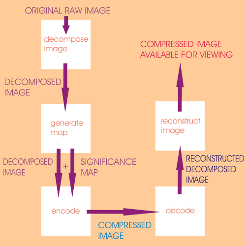
The General Program Flow would be as shown below
![]()